Contact Us
- Building B, No. 17, Zijing Road, Pingxi, Pingdi Street, Longgang District, Shenzhen
- 934728633@qq.com
- +0755-29698036
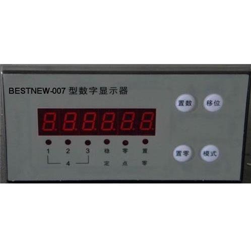
BESTNEW-007 Digital Display
BESTNEW-07 digital display is a multifunctional sensor signal display, which can be used with resistance strain type weighing force measurement/potentiometer type displacement sensor and LVDT type sensor. It has the convenience of full digital calibration and high-precision display practicality, and can be equipped with fixed value control interface/analog output interface/RS-485 digital output interface. It can be widely used in various scientific research and industrial control occasions.
Detailed Introduction
Main performance:
Display: 6-digit LED
Resolution: Maximum 1/50000
Accuracy: 0.01%F. S
*Set value control points: 4 (can be selected as normal set value and selection function)
*Analog output: 12-bit 4~20mA 0~5v/10v optional.
*Digital output: RS-485 baud rate optional.
Appearance: 80×160×130
Power supply: AC 220V
Connection:
The rear panel of BESTNEW-007 is used to connect sensors and power supplies and other output devices:
E+: Connect the positive power supply terminal of the weighing force sensor. For the displacement sensor, it is the negative power supply terminal.
E-: Connect to the negative power supply terminal of the load cell. For the displacement sensor, it is the positive power supply terminal.
IN+: Connect to the positive signal output terminal of the load cell. For the LVDT sensor, it is the negative output signal terminal.
IN-: Connect to the negative signal output terminal of the load cell. For the LVDT sensor, it is the positive output signal terminal. For the potentiometer sensor, it is the signal output terminal of the sensor.
16: Analog output positive terminal
17: Analog output negative terminal.
1: RS-485 output A
2: RS-485 output B.
1# 2# 3# 4# are the 4 setting control relay output terminals. (Please specify normally closed/closed open when ordering)
AC 220V AC power input terminal (DC 24V input terminal)
Front panel:
The front panel of the BESTNEW-007 digital display has 6 LED digital tubes and indicator lights and 4 buttons. The 6 digital tubes are used to display measurement data and set parameters. The indicator light shows the working status. The 4 buttons are used for function operation and data input.
Zero setting: Use the current data as the zero reference.
Mode: Used to set the set control value.
Shift: Used to select the position of the set value when entering data.
Set number: Use the shift key to enter the appropriate data.
Operation:
The sensor must be correctly connected before the BESTNEW-007 digital display is powered on. Otherwise, the display will show an error when it is turned on.
Press the zero key for 2 seconds to reset the current display value to zero.
Press the mode key and the display shows: setup. Press the shift key to enter the set value setting state. The display shows: 1XXXXX
Use the shift and set keys to enter the required value and press the mode key to end. The display shows: 2XXXXXX. Use the shift and set keys to enter the required data and press the mode key to end and enter the next step. . . . . . . . . When there is no need to modify the set data, press the mode key directly until it returns to the normal display state.
Note: Set value 1 < Set value 2 < Set value 3 < Set value 4
Calibration:
The calibration of the BESTNEW-007 digital display requires the following operations:
Press and hold the zero key in the off state and turn on the power. After the display self-checks, press the mode key, the display shows: CAL SP, press the shift key to enter the calibration program, otherwise press the mode key
The display shows: SET, press the shift key to enter the basic parameter setting program,
Otherwise, press the mode key to display: A/D, press the shift key to enter the display A/D conversion internal code state.
Press the mode key, the display shows: d/A, press the shift key to enter the analog output setting.
Before calibration, basic parameter settings should be performed:
After entering the basic parameter setting program, the display shows: d xx n is the division value (resolution), use the setting key to select the appropriate division value, and use the mode key to confirm. After confirmation, the display shows: n xxxx represents the display division number (display accuracy, division value × division value = display range), and the shift and setting keys can be used to enter a new division number. After the division number is confirmed, press the mode key and the display shows: FLt xx to enter the filter parameter setting. You can use the shift and set keys to enter new parameters. The smaller the value, the faster the display response. Press the mode key and the display shows: b xxxx. At this time, you can set the baud rate of the RS-485 interface. After setting, press the mode key to return to the normal display state.
After entering the calibration process, the display shows: CAL 00 to enter the zero calibration. After confirming the zero position, press the mode key. The display shows------After a few seconds, the maximum measurement value XXXXX is displayed. Load the measurement value (if the maximum measurement value cannot be loaded, use the shift and set keys to enter the new load value). After loading, press the mode key to confirm. After a few seconds, the calibration ends and returns to the normal display state.
After calibration, the power must be turned off and then turned on again for normal use.
Analog output adjustment:
After entering the analog output setting program, the display shows: dA XXX indicates analog output zero position, press the set key to increase the analog output value, press the shift key to decrease the analog output value, and press the mode key to confirm when the required value is adjusted. The display shows: FU XXX enters the analog output full-scale adjustment, press the set key to increase the output value, press the shift key to decrease the output value, and press the mode key to end the adjustment when the required value is reached.
You might also like

